
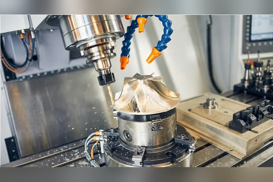
CNC machining can be used to convert digital designs into accurate physical parts, but not all geometries require the same level of manufacturing. The sizes of parts, internal features, wall thickness, and dimensional requirements directly affect the cost of machining and the production time. It is in the engineer’s interest to understand these relationships to design something that is useful without compromising on functionality. Optimized geometry eliminates unnecessary operations, makes access to the tool easier, and also makes it possible to produce the item quickly while maintaining the required accuracy and structural performance.
Understanding the Relationship Between Part Geometry and Machining Efficiency
How a CNC machine approaches the part, cuts it, and finishes it depends on the geometry of the part. Fewer machining operations are typically needed for simple shapes like flat plates, cylindrical shafts, and mounting brackets. More complex designs with deep cavities, curved surfaces, narrow slots, and complex contours demand more programming and special tooling. All of these requirements increase the time and the manufacturing costs of the machining process. Geometry also influences material removal, stability of the workpieces, and inspection requirements. Therefore, complexity assessment of the manufactured product in the design stage helps to establish realistic budgets and production schedules.
Feature Complexity and Its Influence on CNC Machining Costs
Each added feature adds another manufacturing consideration. Different shapes, holes, intersecting slots, recessed pockets, and detailed profiles may need different cutting tools and machining strategies. Multiple repositioning operations or special multi-axis equipment may be required for complex components. This is especially crucial when you’re using CNC machining prototyping services to test functional components prior to production. Engineers can determine if features are not required, and they can simplify the geometry without impacting key performance. Less machining results in faster production, especially if there are many intricate details on the parts.
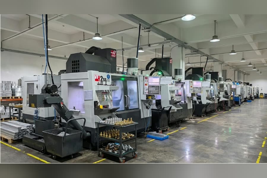
Wall Thickness, Cavity Depth, and Structural Stability
The thin wall and deep cavity structures make it difficult due to vibration, deformation, and dimensional error caused by cutting forces. Such issues are more evident when dealing with flexible materials and when large material is being removed from a small part. Longer cutting tools are also needed for deep cavities, contributing to tool deflection and chatter. Before making a final CAD, designers need to think about realistic geometric restrictions.
Several design considerations help control these challenges:
- Wall Thickness: Metal components generally benefit from minimum wall thicknesses around 0.8 mm, while plastic components commonly require approximately 1.5 mm, depending on material and geometry.
- Cavity Depth: Keeping cavity depth within approximately four times its width helps reduce vibration and tool deflection.
- Internal Corners: Larger internal radii allow thicker cutting tools, improving machining efficiency and reducing unnecessary tool stress.
- Hole Dimensions: Standard drill sizes simplify tooling requirements. Hole depths should generally remain within ten times their diameter.
- Undercuts: Unnecessary undercuts introduce specialized tooling requirements and can increase machining time.
Following these principles improves dimensional stability while limiting avoidable manufacturing complications.
Part Orientation, Tool Accessibility, and Machining Setups
The position of the features affects the accessibility of the cutting tools to various surfaces. In traditional 3-axis milling, it is difficult to machine the features of multiple faces without repositioning the workpiece. Every extra setup adds additional handling time, alignment considerations, and opportunities for positioning errors. Hole, slot, and pocket designs can be combined on surfaces that are easy to access, which can help lower production costs. Four-axis and 5-axis machining offer more access to more complex shapes; however, the machine to be used will depend on the component requirements. Fewer setups can be achieved by combining multiple operations, which will improve accuracy and shorten production schedules.
Material Selection and Geometry Work Together
The properties of a material affect the efficiency of machining a certain geometry. Aluminium is normally very easy to machine and can be used to fabricate complex housings, brackets, and lightweight parts. The cutting conditions are different for stainless steel as it is strong and has different machining properties. If the parts are thin-walled or have complex geometry, more advanced machining processes might be needed for titanium. Also, the behavior of engineering plastics is different in terms of cutting forces and heat. For example, POM is more dimensionally stable than softer plastics, which may require additional precautions to prevent distortion. With the proper material selection, geometry can control machining time, tooling requirements, and manufacturing costs.
Tolerances and Surface Requirements Increase Manufacturing Effort
One thing that is very costly is combining the geometric complexity with extremely tight tolerances. A part that is required to be manufactured to a tolerance of plus or minus 0.01 mm might require further finishing, work holding, and inspection than a part that adopts standard manufacturing tolerances. Temperatures may also need to be controlled, and special measuring equipment is required to keep the dimensions tight for multiple features that are interconnected. Surface requirements generate similar issues. In general, an as-machined finish will not require extra processing, while anodizing, polishing, powder coating, or electroplating will add extra steps. Engineers should avoid the use of unnecessary tolerances and finishes.
Designing Geometry for Faster Production and Predictable Delivery
Design for manufacturability (DFM) is a way to find out the geometric issues before manufacturing. An effective review takes into account the following: machine accessibility, material behavior, cutting-tool dimensions, tolerances, and workpiece stability. 3ERP has been helping with rapid manufacturing projects since 2010, helping with CNC machining and other manufacturing technologies. It uses its engineering team to review CAD models to find ways to simplify features and improve manufacturing efficiencies. Lead times for simple components can be as short as three days, depending on complexity, material availability, quantities, and finishing requirements. The early technical discussions can help to define more realistic production expectations.
Reviewing a model early also pays off, and our article on real-time 3D visualization in product design shows how visual checks catch problems before manufacturing begins.
Conclusion
The geometry of the part is a critical factor in CNC machining cost and lead time. Operations such as deep cavities, thin walls, inaccessible features, complex contours, and unnecessarily close tolerances can add extra operations and manufacturing difficulties. But with careful design, these needs can be minimized without compromising the vital functions. The geometry, materials, position of features, and finishing requirements should all be considered in conjunction with each other, and not as separate factors. 3ERP can take a practical CAD design to accurately manufactured parts with the right type of DFM support and manufacturing know-how. The optimized parts end up helping to facilitate efficient production, cost control, and predictable delivery times.